Project record / Project
Raspberry Pi Audio Switcher HAT
A compact, perfboard-based Raspberry Pi HAT that automatically switches stereo audio sources using a GPIO-controlled relay when an AirPlay 2 client connects.

Overview
TL;DR
Designed and built a compact, perfboard-based audio switching HAT for a Raspberry Pi 3B, replacing a bulky external two-channel relay module. The system uses Shairport Sync as an AirPlay 2 receiver and automatically switches stereo audio connections through a GPIO-controlled DS2Y-S-5V relay when an AirPlay client connects. The completed HAT provides a standalone intermediate solution ahead of a separately designed custom audio PCB.
Key points
Features
- Automatic audio switching triggered by AirPlay 2 connections
- Shairport Sync AirPlay 2 receiver
- Stereo audio routing through a DPDT relay
- Three 3.5 mm stereo audio sockets
- Common ground with switched left and right audio channels
- GPIO 17 control through a BC547B transistor
- 1 kΩ base resistor and 47 kΩ base pulldown resistor
- 1N4007 flyback diode for relay coil protection
- Compact perfboard construction mounted directly on the Raspberry Pi
- Single-relay design replacing a two-channel relay breakout module
Entry 01
Problem
The original audio switching setup relied on a two-channel relay breakout board connected to a Raspberry Pi. The relay module was installed in a separate plastic enclosure, resulting in a bulky assembly with extensive wiring between the Raspberry Pi, the relay board and the audio connectors.

Although this arrangement provided the required audio switching functionality, it was unnecessarily complicated for its intended purpose.
The Raspberry Pi was already being used as an AirPlay receiver, and the audio connections needed to be switched manually. The goal was to automatically switch the audio input when connecting via AirPlay while replacing the external relay module with a smaller, cleaner and more integrated hardware solution.
A custom audio HAT PCB had already been designed as a future replacement. However, because that PCB had not yet been fabricated, a compact intermediate solution was needed.
The main objectives were to reduce the size of the existing hardware, simplify the switching circuitry and mount the complete assembly directly onto the Raspberry Pi.
Entry 02
Solution
The original relay breakout board was replaced by a purpose-built audio switching HAT assembled on perfboard.
Instead of a two-channel relay module, the new design uses a single DS2Y-S-5V DPDT relay to switch both stereo audio channels simultaneously.
A BC547B NPN transistor drives the relay coil, allowing the Raspberry Pi to control the switching state through GPIO 17. The supporting circuit consists of a 1 kΩ base resistor, a 47 kΩ base pulldown resistor and a 1N4007 flyback diode.
Three 3.5 mm stereo audio sockets provide the audio connections. Their ground terminals are connected together, while the left and right signal channels are routed through the relay contacts.
The Raspberry Pi runs Shairport Sync and operates as an AirPlay 2 receiver. A script automatically controls the relay when an AirPlay client connects, allowing the selected audio connection to change without manual intervention.
The relay, driver circuit, GPIO connector and audio sockets were combined into a compact perfboard assembly designed to mount directly onto the Raspberry Pi 3B.
The result is a completed standalone audio switching HAT that replaces the previous external relay arrangement while serving as an intermediate hardware version before the custom PCB is fabricated.
Entry 03
Architecture
The system consists of three main functional parts: the Raspberry Pi and its AirPlay software, the GPIO-controlled relay driver, and the analog stereo audio switching circuit.
AirPlay Receiver and Control
The Raspberry Pi 3B runs Shairport Sync, which enables it to operate as an AirPlay 2 receiver.
A separate control script handles automatic switching when an AirPlay client connects to the Raspberry Pi.
GPIO 17 provides the control signal for the relay driver. This allows the software to change the relay state without directly supplying the current required by the relay coil.
Relay Driver
The relay driver uses a BC547B NPN transistor in a low-side switching configuration.
GPIO 17 connects to the transistor base through a 1 kΩ resistor. A 47 kΩ resistor connects the base to ground, providing a defined low state when the GPIO signal is inactive.
The transistor switches the 5 V relay coil, while a 1N4007 diode is connected across the coil to suppress the inductive voltage transient when the transistor turns off.
The driver consists of:
- 1× BC547B NPN transistor
- 1× 1 kΩ base resistor
- 1× 47 kΩ base pulldown resistor
- 1× 1N4007 flyback diode
- 1× DS2Y-S-5V DPDT relay
Stereo Audio Routing
The audio switching circuit uses three 3.5 mm TRS stereo sockets.
Each socket provides three electrical connections:
- Tip: Left audio channel
- Ring: Right audio channel
- Sleeve: Ground
All sleeve connections are tied together to form a shared ground. The ground connection is therefore not switched by the relay.
The tip and ring connections are routed through the two poles of the DS2Y-S-5V relay, allowing both stereo audio channels to be switched together.
The outermost audio socket is connected to the relay's common (COM) contacts and serves as the output.
The isolated socket, located directly above the Raspberry Pi's built-in audio jack, is connected to one of the switched input paths rather than COM.
The remaining socket provides the other switched audio connection.
This arrangement allows the relay to select between the two stereo signal paths while maintaining a common ground and a single output connection.
Physical Integration
The switching circuit is assembled on a small perfboard that connects to the Raspberry Pi through its GPIO header.
The perfboard carries the relay, transistor driver, connecting wires and three audio sockets.
This eliminates the need for the previous separate relay enclosure and consolidates the required switching hardware into a single Raspberry Pi-mounted assembly.
Entry 04
Implementation
Development began by evaluating different relay configurations for replacing the original two-channel breakout board.
Initial Latching Relay Concept
The first design considered using a bistable, or latching, relay.
A latching relay retains its switching state without requiring continuous coil power. This made it an attractive option for reducing the power consumption of a system that might remain in the same audio switching state for extended periods.
However, the latching relay under consideration introduced additional circuit complexity.
The proposed driver involved two transistor stages with corresponding flyback protection. There was also uncertainty about the required relay coil supply voltage and whether an additional DC-DC converter would be necessary.
Because the circuit was intended to fit onto a compact perfboard, the additional components and wiring were undesirable.
An alternative was therefore considered: the DS2Y-S-5V, a conventional non-latching DPDT relay.
Although this relay requires continuous coil power to remain in its energized state, it can be controlled using a single transistor driver.
The simplified circuit was selected for the interim hardware implementation.
Circuit Design
The final circuit uses GPIO 17 to control a BC547B transistor through a 1 kΩ base resistor.
A 47 kΩ resistor connects the transistor base to ground to prevent the base from being left floating when the GPIO is not actively driven.
The transistor controls the relay coil, and a 1N4007 diode provides flyback protection.
A handwritten schematic was prepared to document the relay control circuit and the intended audio connections.

The audio contacts were arranged so that the two stereo channels could be switched together through the DPDT relay, with the three audio socket grounds permanently connected.
Breadboard Prototyping
Before constructing the permanent assembly, the simplified relay driver circuit was assembled on a breadboard.

The breadboard prototype included the relay, transistor, supporting resistors and connecting wires.
This provided an intermediate stage between the hand-drawn schematic and the final soldered implementation.
The breadboard arrangement was subsequently replaced by a more compact perfboard construction.
Perfboard Assembly
The completed circuit was assembled on a small perfboard.
The DS2Y-S-5V relay, driver components, Raspberry Pi GPIO connector and three 3.5 mm audio sockets were arranged to fit within the available board area.
Electrical connections were made by hand using soldered joints and connecting wires.
The relay and audio connectors were integrated directly into the HAT rather than being housed in a separate enclosure.
The finished assembly was mounted on the Raspberry Pi 3B through its GPIO header.


Software Integration
The Raspberry Pi runs Shairport Sync, functioning as an AirPlay 2 audio receiver.
A control script automatically changes the relay state when an AirPlay client connects.
The script operates GPIO 17, which controls the BC547B transistor and therefore the DS2Y-S-5V relay.
This connects the software-driven AirPlay functionality to the analog audio switching circuit.
Entry 05
Biggest challenge
The main engineering tradeoff was deciding whether the circuit should use a latching relay or a conventional monostable relay.
The original motivation for a latching relay was power efficiency.
Because a latching relay maintains its position without continuous coil power, it could avoid the steady-state power consumption associated with energizing a conventional relay.
However, this benefit had to be balanced against the complexity of the driver circuitry.
The latching relay design under consideration required two transistor drivers and additional protection components. The relay's supply requirements also raised the possibility of needing an additional DC-DC converter.
This conflicted with the physical constraints of the project.
The entire circuit was intended to fit onto a small perfboard mounted directly on the Raspberry Pi. Every additional component increased the space required and the amount of point-to-point wiring.
The alternative DS2Y-S-5V relay allowed the control electronics to be reduced to a single BC547B transistor, two resistors and one flyback diode.
The choice therefore came down to two competing priorities:
- Minimizing steady-state relay power consumption
- Minimizing circuit complexity and physical size
For this intermediate implementation, circuit simplicity was prioritized.
The conventional relay was selected despite its requirement for continuous coil power in the energized state.
This eliminated the need for the more involved latching relay driver and made the compact perfboard construction easier to implement.
The project demonstrates how the simplest practical circuit can be preferable to a theoretically more power-efficient design when component count, assembly effort and space are important constraints.
No quantitative power measurements or direct efficiency comparisons between the relay configurations were documented.
Entry 06
Result
The project resulted in a completed, compact audio switching HAT for the Raspberry Pi 3B.
The new hardware replaces the original two-channel relay breakout board and separate plastic enclosure with a single DPDT relay and a small number of supporting components assembled on perfboard.
The completed HAT incorporates three 3.5 mm stereo audio sockets, with shared ground connections and relay-switched left and right audio channels.
The outermost socket serves as the common audio output, while the relay switches between the two stereo signal paths.
The switching circuit is controlled through GPIO 17 using a BC547B transistor driver.
With Shairport Sync running on the Raspberry Pi, the system functions as an AirPlay 2 receiver. A control script automatically switches the relay when an AirPlay client connects.
The resulting assembly consolidates the switching electronics and audio connections directly on top of the Raspberry Pi, removing the need for the previous external relay module.
The hardware is considered a completed project rather than an unfinished prototype.
It also represents an intermediate stage in the development of a more integrated audio system. A separate custom audio HAT PCB has already been designed but has not yet been fabricated.
That PCB is intended as the next hardware iteration and can be linked as a related project on the website.
No quantitative measurements of audio performance, switching latency or long-term reliability were provided.
Tools and platforms
Technologies
- Raspberry Pi 3B
- Shairport Sync
- AirPlay 2
- DS2Y-S-5V
References
Links and downloads
- ShairPortSync Repositoryrepository
Next reading
Related projects
Deep Dive2025
PCM5102A Raspberry Pi Audio HAT
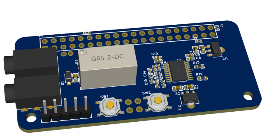
Custom Raspberry Pi audio board combining a PCM5102A I²S DAC with relay switching between DAC audio and an external stereo input.
Electronics · Embedded Systems
- Raspberry Pi Zero 2 W
- PCM5102A
- EasyEDA Pro